Electro-hydraulic power steering - construction and principle of operation
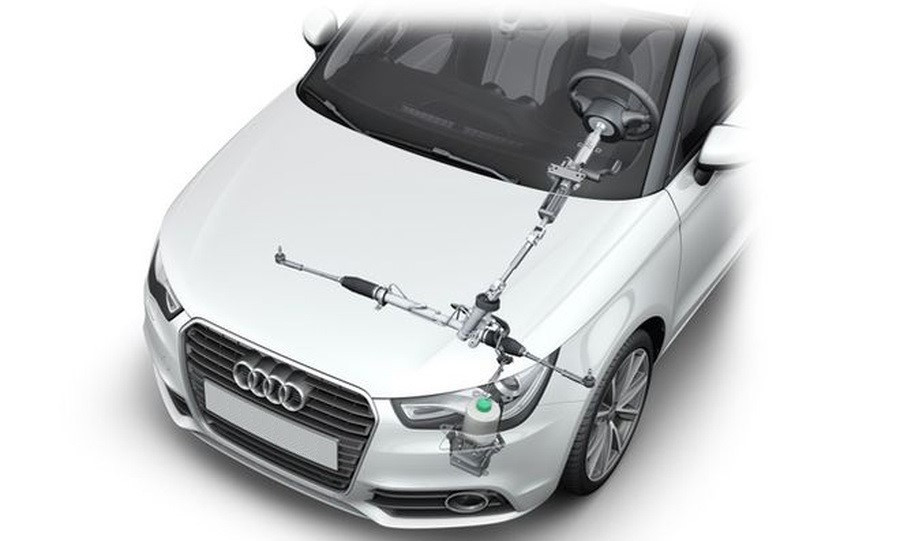
The design of the car's steering system was constantly improving along with its other components. As the speed and weight of carsóve increased, the issue of power steering became important - the driver's muscles were no longer able to cope with manoeuvring and parking.
The first power steering system was hydraulic, driven by a crankshaft via a belt transmission. It is still used today because it is reliable and efficient, but it has significant drawbacks, the main ones being the dependence of the pump output on the engine speed and the constant consumption of some power to turn the hydraulic pump, even if the caród is driving in a straight line. The evolution of the hydraulic booster has been initiated.
How electric power steering was developed
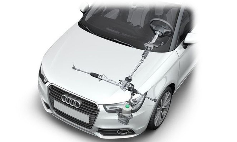
The initial stage of the variable hydraulic system was the servotronic valve, which released pressure in the hydraulic line when the caród moved at high speed. The steering became more flexible and responsive, but this was only half the problem. Traditionally designed power steering systems are very difficult to manoeuvre, especially in traffic when maximum power is required but the engine is usually running at minimum speed. The designers had to design the pump for maximum power and drain excess working fluid at high engine shaft speeds via a bypass.
Also, the servotronic did not solve the mainós problem of the hydraulic system: the constant revolutionsós during internal combustion engine operation and the significant drawbacks that accompany this, such as
- increased fuel consumption and atmospheric emissions;
- faster wear of the power steering pump and reduced fluid quality;
- the presence of a belt drive and, therefore, the attachment to a specific installation location;
Therefore, as the power of automotive generators increased and electronics improved, it became possible to equip the hydraulic pump with an electric motor. Initially, these were collector-type motors. Such pumps were not yet able to change performance, but due to the absence of a drive belt, the unit could be installed anywhere in the engine compartment. The pump's performance ceased to depend directly on engine speed. Later, they were equipped with a soft start system, and then with a control unit for the hydraulic booster with diagnostic capabilities.
Since there were no complaints about the discharge part of the pumps, which is characterized by high quality and performance, further improvement of the units was made by developing electric drive motors. Permanent magnet brushless electric motors (BLDC) were introduced. We will compare all kinds and types of electric motors below.
Structure and operating principle of an electrohydraulic amplifier
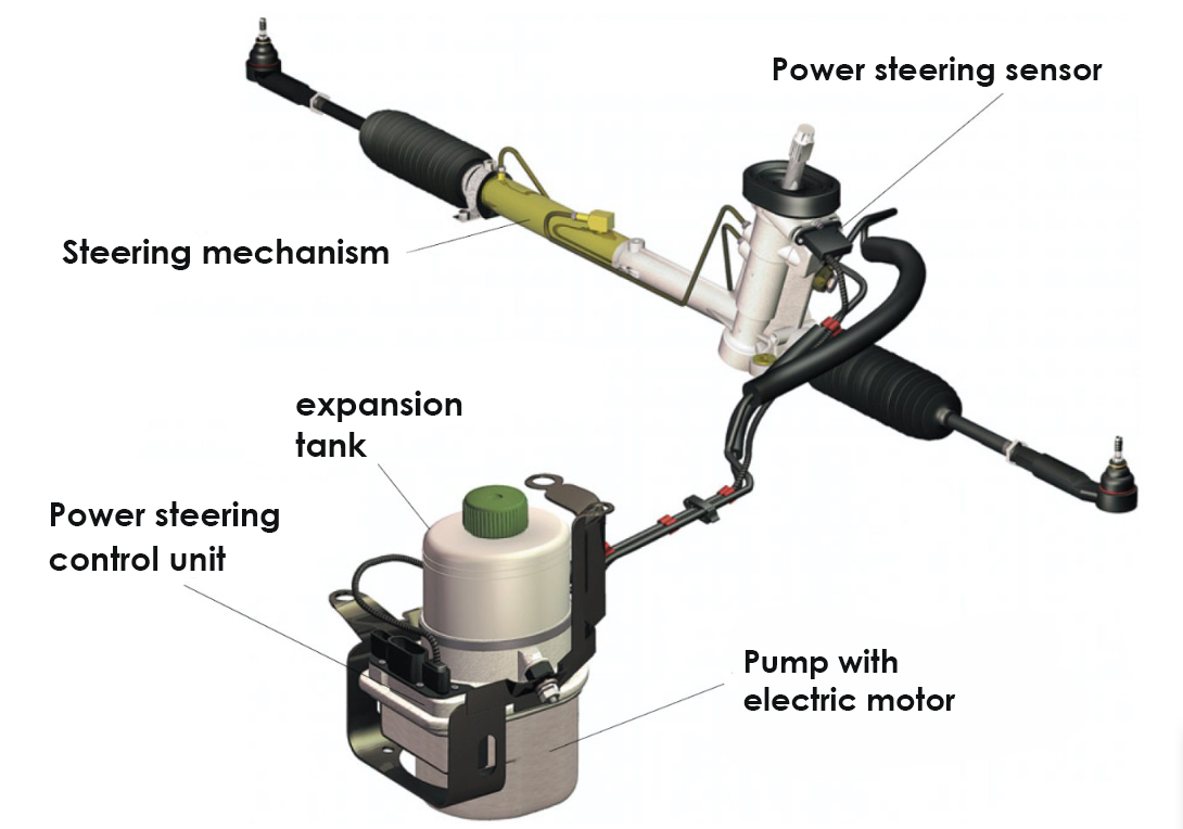
The principle of operation of the former has remained virtually unchanged with the advent of electric motors and the electronics that control them. As before, the driver's steering wheel rotation is amplified by the pressure of the working fluid, although now it is created by a pump with an electric drive independent of the internal combustion engine. Only the rotary spool housing has a power steering sensor that transmits data on the steering wheel rotation speed to the electronic control unit so that it can adjust the pump speed.
The hydraulic power steering system includes:
- pump
- working fluid pressure regulator;
- expansion tank;
- control valve (spool);
- steering rack (or steering gearbox) with a power cylinder;
- high and low pressure hoses.
In addition, the power steering system may additionally include a hydraulic fluid filter and/or cooler.
Pump design and operating principle
The design of this device can be divided into two parts:
- Hydraulic.
- Electric.
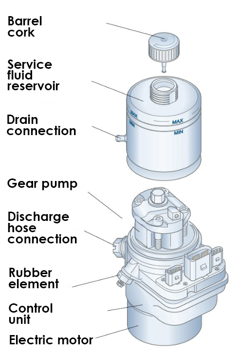
In most carsós they are combined into a single unit. This consists of:
- hydraulic module with gear pump and reducing valve;
- electric motor;
- reservoir for working fluid;
- power steering control unit;
The pump is connected to the steering mechanism via special drain hoses. As in a conventional hydraulic system, the drain line is connected to the breakout tank. In the engine compartment, the pump is attached to a bracket, whichós usually attached to the body or frame carrier by means of resilient rubberóelements.
Structure of the hydraulic part of a power steering pump
The pumping components of power steering pumps can be divided into three types:
- gearbox
- piston
- blade
The most common pumps installed in modern cars are the first type. The reason for this is the relatively simple design, high efficiency and performance.
The rotating gears draw fluid into the space between the teeth and transfer it from the low-pressure zone to the high-pressure zone, thus forcing itób into the network. As there is virtually no gap between the body and the endsóof the teeth, a good seal is ensured. This is supplemented and reinforced on the sides by plates or bushings, which also act as bearings for the gears.
The hydraulic part of the pump is maintenance-free. The hydraulic part of the pump requires no maintenance. Its parts are lubricated with working fluid during operation.
Electrical part
.jpg)
This includes the electric motors that drive the pump and the electronics thatóra control them. Depending on the vehicle model, engine type and otherófactors, this could be a control unit, microcontroller or relay. There are a number of waysór to control the pump electronics:
- Injecting current into the terminal (simplest type).
- Controlling by means of a control unit.
- Control by pulse width modulation (PWM) based on engine speed and vehicle speed sensors.
- Control by pulse width modulation (PWM) based on engine speed and vehicle speed sensors.
- Through the K-line diagnostic interface (used on early generations of EHPC units).
- The CAN bus is the most modern method used in pumps for both control and diagnostics.
Two types of electric motorós are used in electric and electrohydraulic power steering systems:
- collector (brush) motors;
- Brushless (BLDC) motors;
Collector motors were installed earlier and have limited functions. However, they cannot be considered unequivocally inferior, as each of these two typesóof motoróhas its advantages and disadvantages.
Brush manifold engine
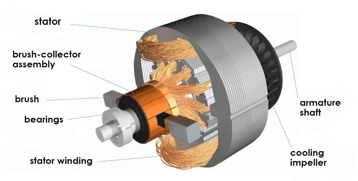
Benefits:
- Ease of manufacture and maintenance.
- Ease of speed control.
- Easy to use.
- Low cost in comparison to BLDC.
- Low cost in comparison to BLDC.
Disadvantages:
- Maintenance of brush-collector assembly.
- Low torque on start-up.
- Low starting torque.
- Lower efficiency.
Brushless motor (BLDC)
.jpg)
Benefits:
- High efficiency and torque values.
- No brushes subject to friction and wear.
- High reliability and long service life.
- Possibility of smooth adjustment of the pump rotation speed.
Weaknesses:
- High cost compared to brushómotors due to the use of expensive magnets.
- More complex electronic control system.
Typical faults of electrohydraulic power steering
Just like the parts of the pumping unit, the breakdowns of the unit can be divided into mechanical and electrical. The most common of the first group are:
- leakage of working fluid due to broken seals or damage to hoses and pipes in the main line;
- contamination of the pressure reducing valve;
- wear of gears.
In the first case, malfunctions can be recognized by oil stains under the car, and in the other cases, by a drop in system pressure and a tight steering wheel.
Electrical breakdowns are more diverse. These are:
- wear or damage to electric motor parts: brushes, windings, collector;
- electronics malfunction: control board, field-effect transistors;
- sensor malfunction;
- Lack of communication with the control unit or control board.
Frequent causes are corrosion of contacts or parts, as well as short circuits associated with the penetration of working fluid into the electronic unit.
Repair of electric power steering
Although manufacturers often recommend replacing the entire unit in the event of a malfunction, the pumps of the power steering system are quite repairable. The main thing is to seek the help of qualified craftsmen - for example, STS, whose specialists have all the necessary equipment for repair, as well as many years of experience in servicing and restoring any steering systems.
